Making Research Move: A Step-by-Step Guide to Spinning Academic Posters
Presenting academic research at conferences is a staple in the journey of any researcher, but making your work stand out can be a challenge. At a recent conference, I wanted to take this challenge head-on. So, I created something different: a spinning academic poster. Not only did it capture the attention of my peers, but I also won a prize from the Royal Society of Chemistry for my efforts.
Here's how I brought the spinning poster concept to life, and the challenges I faced.
The Idea: A New Take on the Traditional Poster
Academic posters typically follow a simple format: static, two-dimensional, and often confined to a few key sections of a researcher's work. While effective, they can lack engagement, especially in a room full of similar posters. I wanted to find a way to give my research a more dynamic presence.
The solution? A rotating or "spinning" poster. Inspired by manual spinning posters which have cropped up at various conferences across the world recently, I wanted to take this one step further. I decided to add an element of automated movement.
1. The Poster Design
The first challenge was to design a poster that incorporated a rotating section. This required two separate layers:
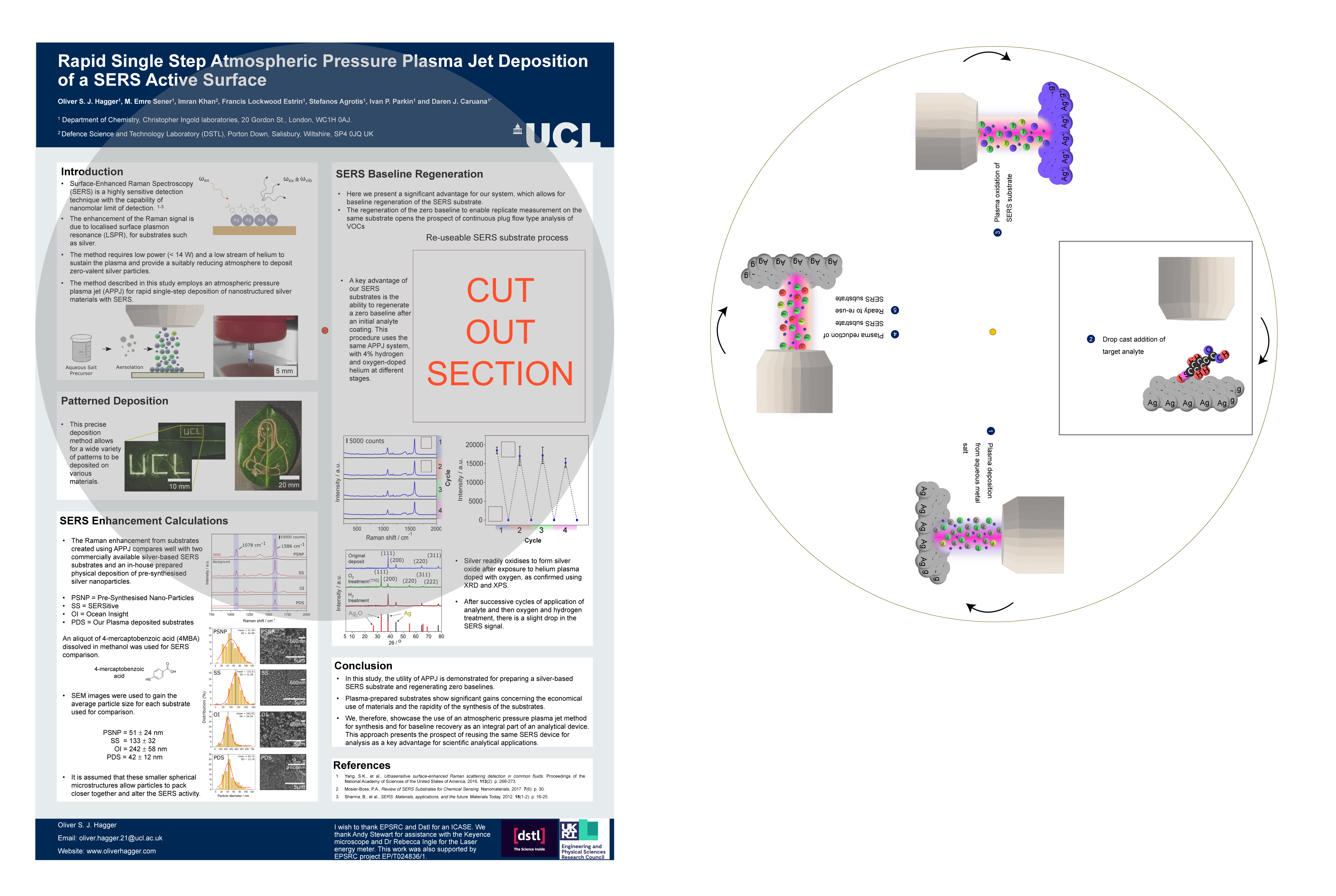
- The Outer Poster: The top layer with a cut-out section to frame the rotating element.
- The Rotating Poster: Positioned behind the top layer, it featured four distinct panels to showcase different parts of the research.
To ensure smooth rotation, the circular rotating section had to fit entirely within the boundaries of the outer poster. Each of the four panels was arranged at 90-degree angles to avoid overlap. This setup allowed viewers to see one scene at a time.

Two poster parts. Overlaying poster (left). Rotating poster part (right).
For structural support, I experimented with materials like cardboard and plastic sheets but ultimately adopted a design inspired by kites. Four rods connected to a central hub provided stability without compromising mobility. To further enhance the structure, I 3D-printed a loop component that was attached to the edge of the spinning poster. This loop allowed the rods to slot through and connect seamlessly to the central hub, ensuring a secure and stable framework while maintaining smooth rotational movement.
2. The Motor and Encoder
Initially, my idea was straightforward: attach a small motor to the centre of the rotating section of the poster, with some form of support to stabilise it. My first choice was a 5V stepper motor (28BYJ-48) with a ULN2003 driver board. To control the motor, I used an Arduino R4 WiFi for precise positioning. The Stepper Motor library from Arduino provided smooth movement during early testing.
However, this motor lacked the torque to rotate the poster. Upgrading to a NEMA17 stepper motor offered more power but introduced a new challenge.
Most poster symposiums lack mains power, so I had to rely on a portable power bank. While many power banks supply only 5V, I sourced one with a 12V output, which provided sufficient torque but caused the motor and driver board to overheat, posing a potential fire hazard. Due to safety regulations, I reverted to a 5V power supply to eliminate overheating risks.

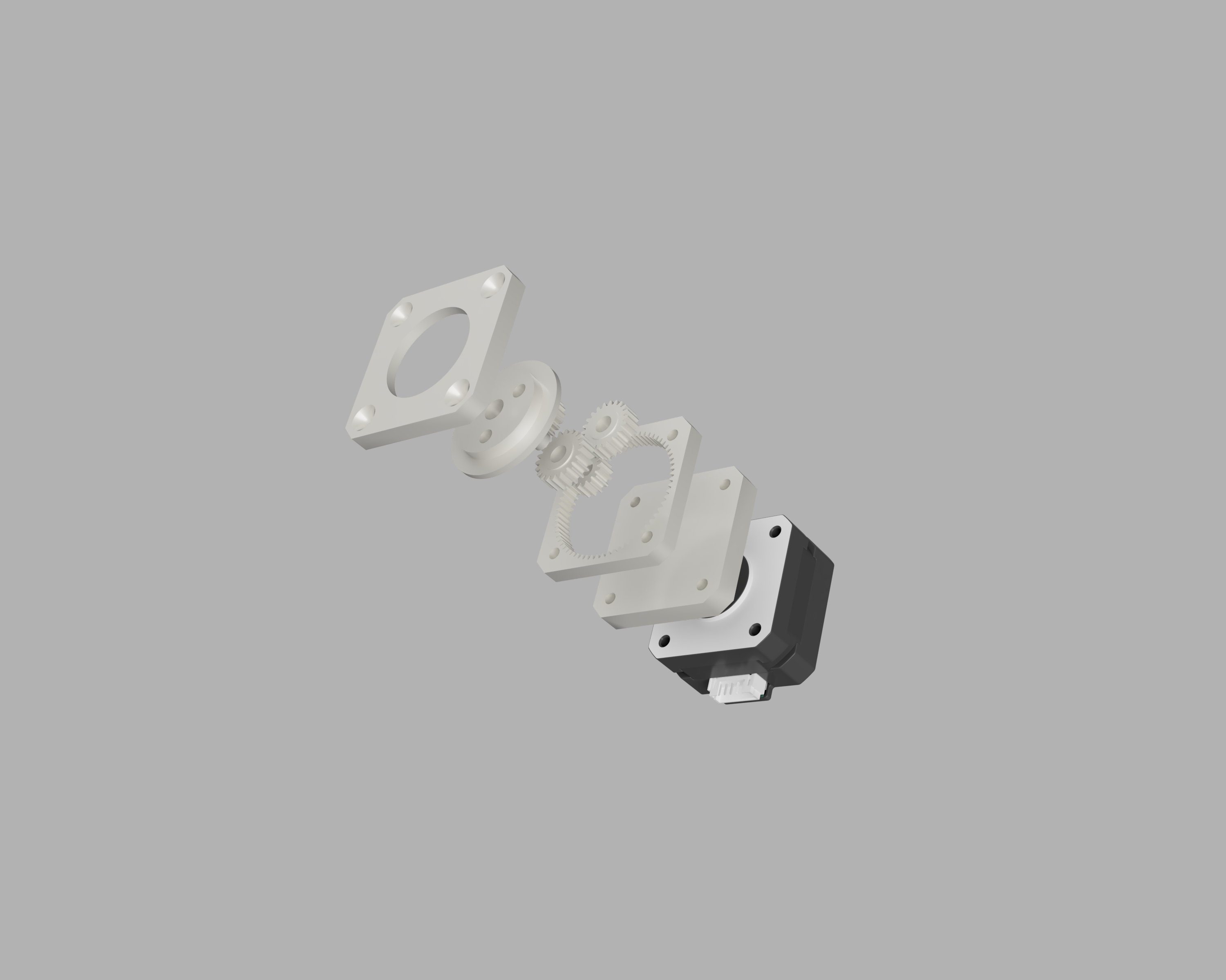
5:1 3D-printed planetary NEMA17 gearbox.
To compensate for the lower voltage, I designed and 3D-printed a 5:1 planetary gearbox. This significantly increased the torque output of the NEMA17 motor while maintaining a compact design, ensuring reliable operation within the safety and power constraints.
The final motor setup included:
- A NEMA17 stepper motor with the custom 3D-printed gearbox.
- An Arduino R4 WIFI with an Arduino motor shield.
- An Ansmann PB212 10,000mAh power bank with dual USB outlets: one powering the motor and the other a small 40 x 40 mm cooling fan for the Arduino board and motor shield.
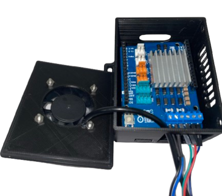
- A custom case for the Arduino, designed to house the 40 x 40 mm fan and ensure proper airflow.

Arduino R4 Wi-Fi and Arduino Motor Shield with a 40 x 40 mm fan, all housed within a custom 3D-printed case.
The speed and delay were adjusted to ensure the movement was slow enough for viewers to read the text but fast enough to maintain a dynamic visual element. Additionally, the step movement was modified from 250 to 267 to overcome the friction between the two posters. With this setup, the motor could smoothly rotate the poster using a simple control loop:
      #include "Stepper.h"

      const int stepsPerRevolution = 200;

      #define pwmA 3
      #define pwmB 11
      #define brakeA 9
      #define brakeB 8
      #define dirA 12
      #define dirB 13

      Stepper myStepper = Stepper(stepsPerRevolution, dirA, dirB);

      void setup() {
        pinMode(pwmA, OUTPUT);
        pinMode(pwmB, OUTPUT);
        pinMode(brakeA, OUTPUT);
        pinMode(brakeB, OUTPUT);

        digitalWrite(pwmA, HIGH);
        digitalWrite(pwmB, HIGH);
        digitalWrite(brakeA, LOW);
        digitalWrite(brakeB, LOW);

        myStepper.setSpeed(30);
      }

      void loop() {
        myStepper.step(267);

        delay(7000);
      }
Code used for controlling NEMA17 stepper motor
3. The Final Poster
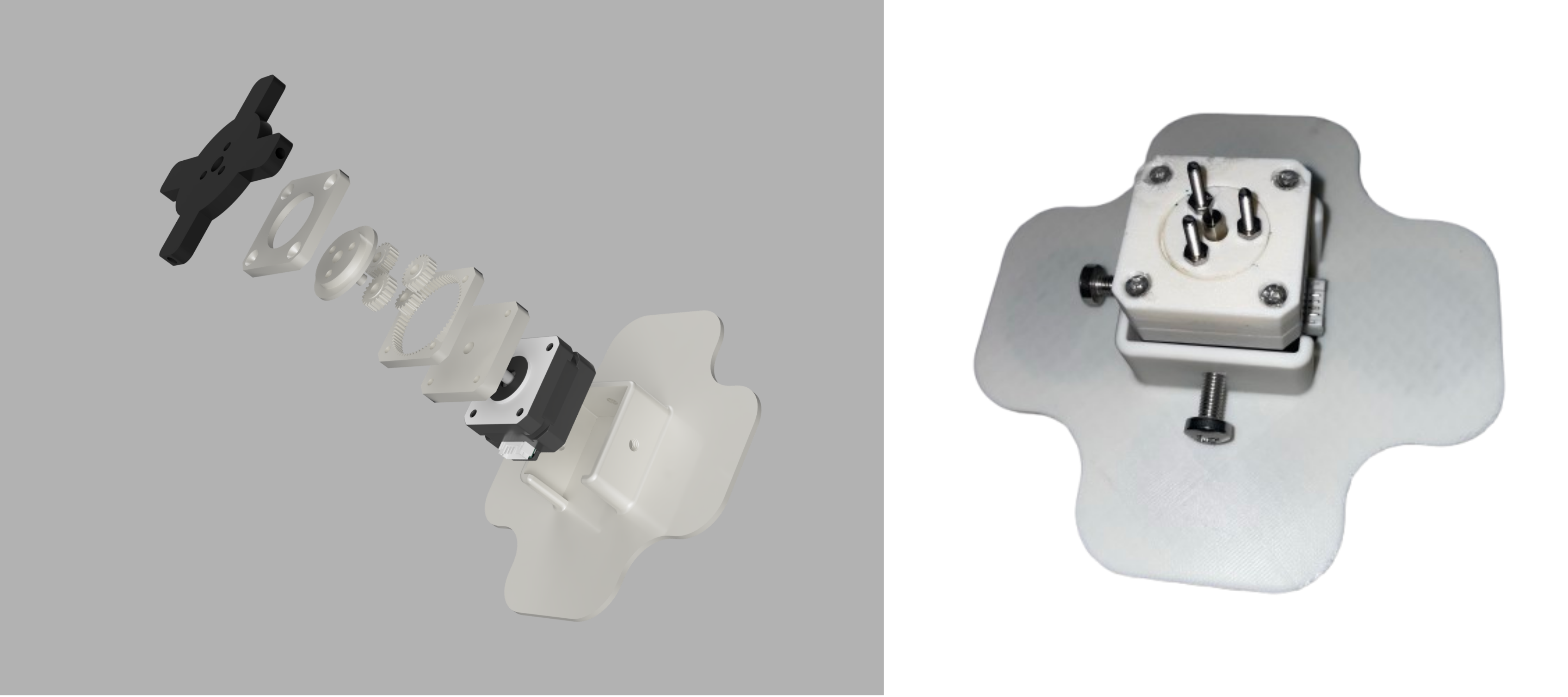
Before the conference, I rehearsed the setup on a poster board, which allowed me to make final adjustments. The gearbox featured three holes through which I inserted screws secured with nuts. These protruding screws served as pins to connect to the spinning poster element, enabling movement without causing damage.

(Left) Complete motor setup, shown from left to right: poster backplate, 5:1 3D-printed planetary NEMA17 gearbox, NEMA17 motor, and NEMA17 housing for attachment to the poster board. (Right) Real NEMA17 motor with protruding screws at the front of the 3D-printed planetary gearbox and NEMA17 housing.
For the final assembly, I 3D-printed a front and a back central panel. The front panel featured holes to accommodate the motor screws, while the back panel included additional holes to secure the rods, ensuring the poster's structural integrity.
The final step involved attaching the poster, along with the geared motor, power bank, and Arduino, to the poster board. To achieve this, VELCRO Industrial Strength Hook & Loop Self-Adhesive Sticky Coins were used.
.png)
VELCRO attached to the back of the NEMA17 housing.
Lessons Learned and Future Plans
While this setup is far from perfect and leaves room for improvement in every aspect, it was an innovative solution given the time constraints. It successfully captured attention and ultimately led to me winning a prize from the Royal Society of Chemistry.
